Technology CMUT - Capacitive Micromachined Ultrasound Transducers: A Primer
ACEP Technology Subcommittee
All images are author’s original.
Capacitive micromachined ultrasound transducers (CMUTs) are micro-electromechanical systems that convert electrical energy into sound waves. This new method of generating ultrasound has seen major developments over the last decade and is now widely available for use. CMUTs are the basic building blocks of ultrasound chips, which have gained notoriety since the launch of the Butterfly iQ, but this technology has existed since the 1990s and there are currently 23 companies experimenting with CMUT based products.1
The traditional method of generating ultrasound waves relies on piezoelectric materials, most often lead zirconate titanate. Transducer arrays are composed of multiple piezoelectric elements surrounded on either side by electrodes (Figure 1). These electrodes apply a charge to the piezoelectric element which causes it to expand and contract, generating the mechanical force to produce an ultrasound wave. The element is struck by returning echoes, converting this mechanical force into a voltage that is received by the electrodes and used to generate an ultrasound image. These arrays require several other layers to function properly. A matching layer covers the active element to buffer the changes in impedance between the piezoelectric material and the patient’s tissues and a backing layer dampens the element to prevent persistent “ringing” and improve the elements ability to receive echos.2 The resonant frequency of a piezoelectric transducer is determined by the thickness and other physical properties of these various layers, which are finely tuned at the time of construction. Construction of these probes rely on traditional manufacturing methods, specialized tooling, and manual labor to mix, grind, heat, mold, and bond materials. The result is a fabrication process with long lead times and poor functional yield, which increases the cost of ultrasound probes.3
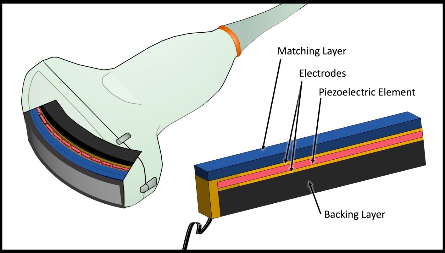
Figure 1: Basic structure of a piezoelectric transducer array.
CMUTs as their name suggests function based on capacitance. At its most basic level a capacitor consists of two parallel electrode plates connected to a power source and separated by an insulator material. When a DC voltage is applied to the system, the electrodes become polarized, with positive charges collecting on one plate and negative charges on the other. The amount of charge that collects between the two plates at a given driving voltage is the capacitance of the system.4 As the distance between the electrode plates decreases, the capacitance of the system increases (Figure 2). Systems with higher capacitance can store more charge at the same driving voltage.
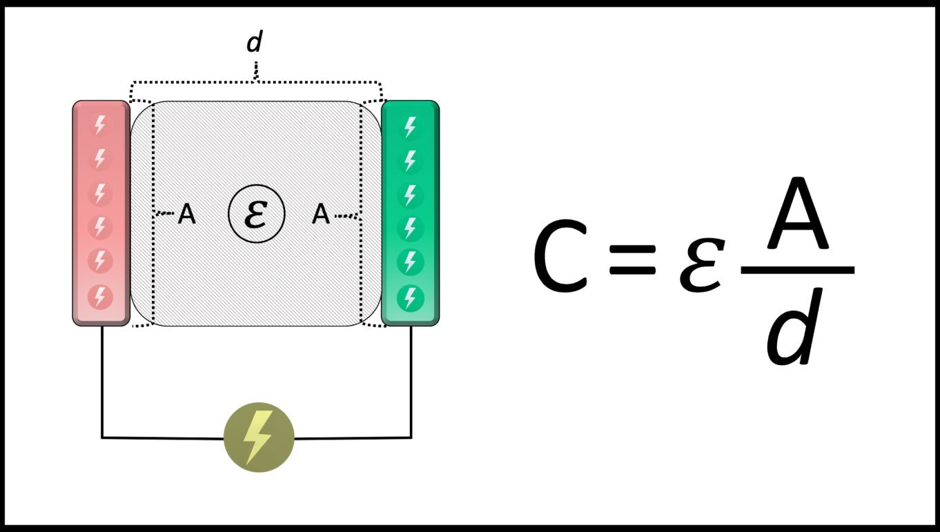
Figure 2: Diagram of a parallel plate capacitor and formula for capacitance. Capacitance (C) is a function of: the permittivity (𝜺) of the insulator material (a measure of the ability of the material to insulate), the area (A) of overlap between the two plates, and the distance (d) between the plates
Now imagine a capacitor in which one of the rigid electrode plates has been replaced with a flexible membrane that can accommodate the same charge. This is the basic construction of a CMUT. When a voltage is applied to the system opposing charges attract, pulling the flexible membrane down. If the applied charge is an alternating current, the membrane will snap back as the current alternates directions, generating the mechanical force to produce sound waves (Figure 3). When a sound wave strikes the membrane, it is deflected down towards the base electrode and vibrates (Figure 4). This changes the distance between the electrodes and therefore the capacitance of the system, generating a current flow. This current fluctuation can be used to determine the strength and location of the returning echoes to create an ultrasound image. For the system to detect returning ultrasound waves, it must be biased with a small direct current to sense changes in capacitance.
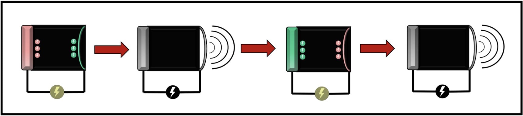
Figure 3: CMUT ultrasound transmission utilizing an alternating current
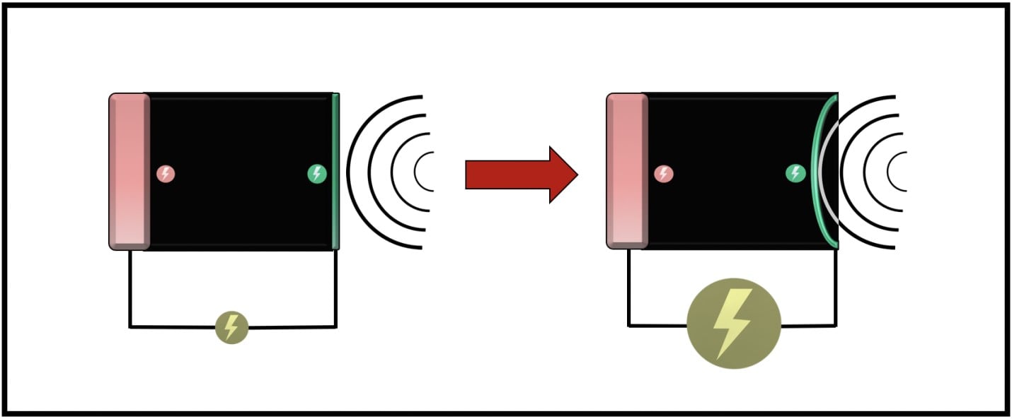
Figure 4: CMUT ultrasound reception utilizing and direct current and changes in capacitance
This is not a new concept; condenser microphones have functioned based on this principle since their invention in 1916. Soundwaves strike a flexible charged membrane in the microphone which vibrates over a fixed electrode plate to generate a fluctuating electrical current used for recording. In order to drive a condenser microphone to vibrate at ultrasonic frequencies, you would need massive voltages that would cause the air in the insulator gap to break down and form a conductive arc between the electrodes, shorting out the system.5 Things function differently at the micro level, CMUTs are capable of supporting extremely high voltages because the distance between the electrodes is extremely small, resulting in a large increase in capacitance.
Fabrication of these microelectric capacitors requires specialized micromachining techniques like thin-film deposition, etching, and photolithography. Construction of a CMUT begins with a silicon wafer that serves as the bottom electrode, a silicon membrane is etched on top, and the compartment between the two is vacuum sealed (Figure 5).6 These individual units can be arranged in transducer arrays of virtually any size or geometry (Figure 6). Ultrasound chips are produced using the same automated supply chain that already exists to create the chips for cell phones and computers. CMUTs can be manufactured precisely and inexpensively, eliminating the time intensive labor and potential for error that comes with constructing piezoelectric arrays by hand.
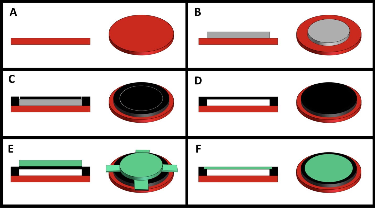
Figure 5: One Method of CMUT Fabrication, (A) A silicon wafer serves as the base substrate, (B) A sacrificial layer of polysilicon is used to maintain the space between the electrodes, (C) A silicon membrane is deposited onto the substrate, (D) The membrane is etched to the initial silicon substrate, the polysilicon layer is chemically removed and the gap is vacuum sealed, (E) aluminum is deposed in a pattern to serve as the top electrode and the electrical connections, or (F) the membrane itself can serve as the top electrode
Furthermore, much of the matching layer, backing layer, and circuitry present in piezoelectric probes are not necessary for the ultrasound chip to function. This opens up room within the probe to incorporate the central processing unit of the ultrasound. Another advantage of housing ultrasound transducer on a silicon chip is that there are numerous ways to easily connect them to the microprocessors that generate images. The CMUT can be built directly on top of the front end electronics of the ultrasound at the time of fabrication or laid back to back later with flip chip bonding.1 A lot of the computation that goes into producing ultrasound images can be done within the probe, allowing the image to be displayed on a smartphone.
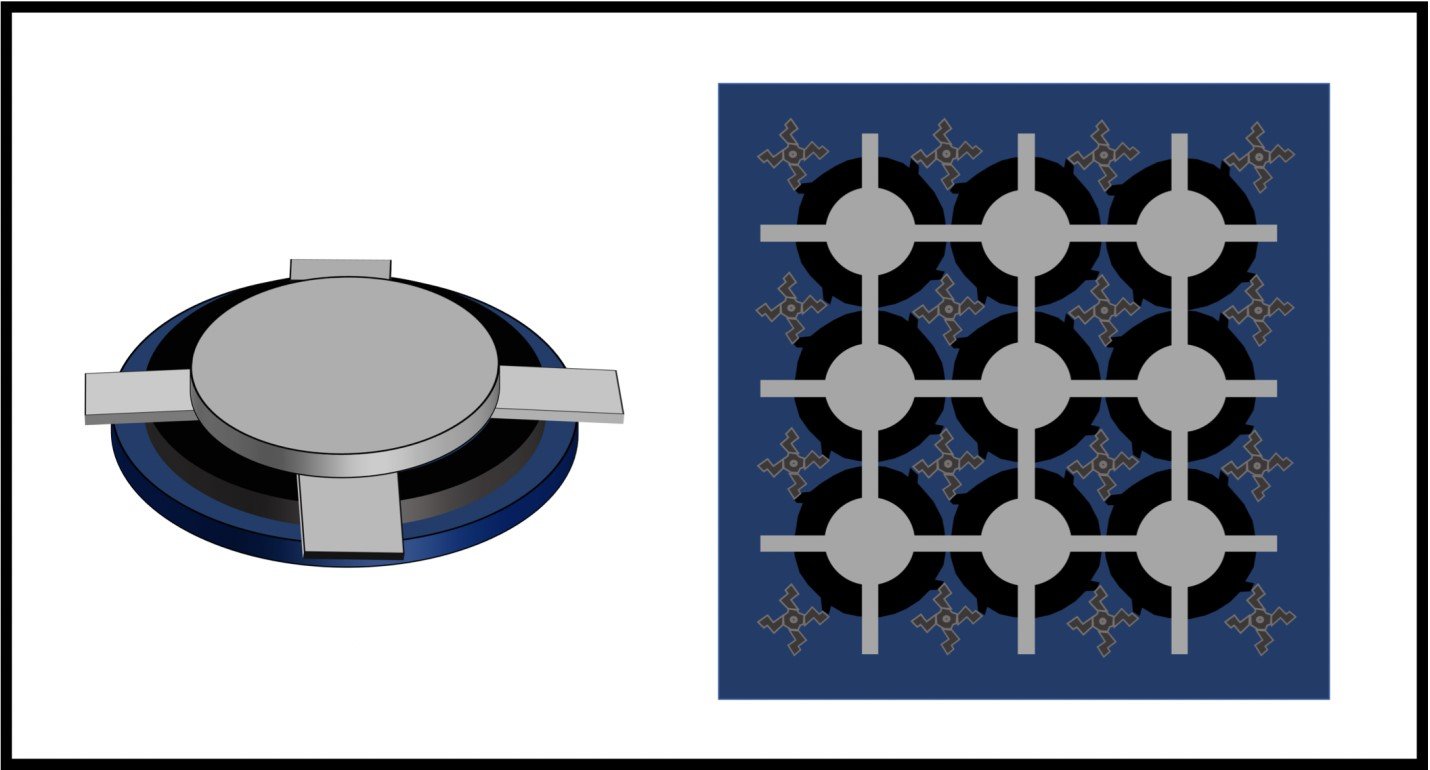
Figure 6: Single CMUT and CMUT array on silicon wafer
Much of the important work in developing functional CMUTs was conducted by the Khuri-Yakub group at Stanford. They initially began experimenting with applications in air (non-destructive testing), but eventually discovered the impressive fractional bandwidth of these transducers after submerging them in water. Piezoelectric transducers have a distinct resonant frequency, the active elements oscillate well with minimal driving energy at this frequency and poorly at others. CMUTs have a similar narrow operating frequency in air, however when they are immersed in water (or applied to a patient’s body with gel), because the silicon membrane has such little mass, it becomes over dampened and can be driven to operate at much higher and lower frequencies. The group's investigators compare this property to a pendulum, which easily swings back and forth at a specific frequency in air based on its construction, but can be driven to operate at other frequencies with less energy when its movement is dampened by submersion in water.5 This allows one CMUT based probe to operate over all the frequencies necessary for medical imaging, eliminating the need for multiple transducers.
We shouldn’t expect CMUT based probes to fully replace their piezoelectric counterparts, but micro-electromechanical technology offers several advantages over traditional probes. CMUTs are produced with less costly, automated manufacturing techniques making these probes more affordable. Their small size and easy integration with the ultrasound central processing unit results in CMUT based transducers that are highly portable and capable of functioning with only the addition of a smartphone or tablet. Finally, the large fractional bandwidth enables one probe to image across the entire frequency range necessary for patient care. All these advantages have decidedly positive implications for the use of ultrasound in emergency medicine, education, EMS, and global health.
References
- Brenner K, Ergun AS, Firouzi K, et al. Advances in capacitive micromachined ultrasonic transducers. Micromachines. 2019, Feb 23;10(2).
- Genovese M. Ultrasound transducers. J Diag Med Sonography. 2016, 32(1), 48–53.
- Broschart B. Why do ultrasound probes cost so much?: The expense behind transducer technology. A conquest imaging white paper. April 2019.
- Hooge, Charles. OpenStax, College Physics. Chapter 19.5: Capacitors and Dielectrics. OpenStax CNX. Aug 22, 2016.
- Khuri-Yakub B, Oralkan M, Kupnik M. Next-gen ultrasound: Medical imaging borrows. Techniques from the microelectronics industry. IEEE Spectrum. May 1st, 2009.
- Ergun AS, Oralkan O, Yarahoglu GG, et al. Capacitive micromachined ultrasonic transducers: fabrication technology. IEEE Trans Ultrason Ferroelectris Freq Control. 2005; 52(12):2242-2258.
Jacob Schoeneck, MD
Assistant Professor and Director of Emergency Ultrasound, Wake Forest Baptist Hospital.